



Flange Sealing Face Types for Instrumentation: RF, FF, RJ, MFM, TG
2026-07-31 08:55Flange Sealing Face Types for Instrumentation: RF, FF, RJ, MFM, TG

Flange connections are ubiquitous in chemical instrumentation installation, applied to pressure/differential pressure transmitters, flow meters, level gauges, control valves, instrument sampling valves and more. The type of flange sealing face directly determines gasket selection and sealing reliability. This article elaborates on five most common sealing faces widely used in chemical instruments: FF (Flat Face), RF (Raised Face), MFM (Male & Female), TG (Tongue & Groove), RJ (Ring Joint), along with their corresponding instrument application scenarios.
1. Common Standards & Sizes of Instrument Flanges
Process connection flanges for instruments mainly comply with the following specifications:
ANSI/ASME B16.5 (American standard, Class 150 / 300 / 600 / 900 / 1500 / 2500)
EN 1092-1 (European standard, PN series)
DIN (German standard, gradually replaced by EN standards)
GB/T 9112~9124 (Chinese national standard, referenced from ISO and EN)
Small-bore flanges widely adopted for instruments: 1/2", 1", 1½", 2". Coplanar flanges integrated on differential pressure transmitter bodies fall into this category. Partial instruments adopt flange dimensions specified in EN 61518 (Process measurement and control equipment process connection standard), which are essentially consistent with general flange standards.
2. Five Types of Sealing Faces (From Instrument Application Perspective)
2.1 FF – Flat Face
Applicable instrument scenarios: Sampling valves and pressure gauge connections on instrument air, water and low-pressure steam pipelines with low pressure ratings (≤Class 150 / PN16). Commonly matched with cast iron valves or lined flanged instruments.
Gasket requirement: Full-faced non-metallic flat gaskets covering the entire flange surface.
Note: FF flanges cannot be mated with RF flanges, otherwise the gasket will bear uneven compression and cause leakage.
2.2 RF – Raised Face
Applicable instrument scenarios: The most prevalent connection face in chemical plants. Most transmitters, flow meters and control valves are equipped with RF faces, covering pressure grades from Class 150 to Class 900 (PN16~PN160).
Gasket requirement: Universal spiral wound gaskets (with or without inner ring), metal toothed gaskets and PTFE encapsulated gaskets. The gasket must be accurately centered on the raised ridge without offset during installation.
Critical reminder: Small RF flanges at transmitter pressure tapping ports are often overlooked. Replacement gaskets shall be sized matched spiral wound gaskets; self-made rubber gaskets are prohibited.
2.3 MFM – Male & Female Face
Applicable instrument scenarios: Control valves and orifice plate flanges adopted with MFM faces for enhanced sealing safety under medium-to-high pressure (Class 300~900) or toxic, explosive media.
Gasket requirement: Flat non-metallic or metal-clad gaskets fitted inside the female recess, with outer diameter slightly smaller than the groove size.
Installation tip: Male flange must align perfectly with female flange; misalignment will lead to sealing failure. Most instrument manufacturers stamp "M" (male) and "F" (female) marks on flange outer rims for identification.
2.4 TG – Tongue & Groove Face
Applicable instrument scenarios: Instrument piping connections under high vacuum, highly toxic media (phosgene, hydrogen fluoride) or high-temperature high-pressure steam. TG delivers superior sealing performance over MFM, yet the tongue ridge is vulnerable to damage during disassembly. Thus TG is rarely fitted on regular instruments, only adopted for special-condition orifice flanges and instrument root valves.
Gasket requirement: Solid metal ring gaskets or custom flat gaskets seated within the groove.
2.5 RJ – Ring Joint Face
Applicable instrument scenarios: Instruments (pressure transmitters, orifice flow meters) installed on high-pressure natural gas, hydrogenation units and ultra-high pressure steam pipelines, pressure rating Class 600~2500.
Gasket requirement: Oval or octagonal metal ring gaskets (soft iron, stainless steel, Cr-Mo steel etc.).
Key notes: RJ flanges cannot mate with any other sealing face types. The ring joint groove must remain clean and scratch-free. Bolt preload torque for RJ flanges shall be calculated per standard specifications; excessive tightening will permanently damage the flange groove.
3. Common Misoperations for Instrument Flange Sealing Installation
❌ Mistake 1: Using full-faced FF gaskets on RF flanges
The inner part of the gasket bears excessive pressure while the outer edge hangs unsupported, resulting in frequent leakage. RF instrument flanges must adopt size-matched spiral wound gaskets or inner-ring reinforced gaskets.
❌ Mistake 2: Random replacement of original instrument flange gaskets
Instrument manufacturers supply matched gaskets with identical material as standard accessories. Ordinary rubber gaskets shall not substitute factory originals, especially under high temperature and high pressure working conditions.
❌ Mistake 3: Neglecting cleaning of trapezoidal grooves before RJ face assembly
Hard particles trapped inside ring joint grooves create uneven indentations on metal ring gaskets and permanent groove damage, causing persistent leakage. Clean thoroughly with lint-free cloth and solvent before fitting.
❌ Mistake 4: Mismatched flanges of different pressure grades or standards
Class 150 RF flanges and PN16 RF flanges feature similar pressure resistance but differ in bolt hole dimension and sealing ridge height, and cannot be forced together. Clarify unified flange standards during instrument procurement.
4. Quick On-site Identification Methods for Instrument Flange Sealing Faces
Check nameplates or flange stamp marks: Qualified instrument flanges are engraved with standard code, pressure rating and sealing face type, e.g. "ASME B16.5 Class 300 RF".
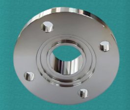
Visual inspection of surface profile: RF features a prominent raised ridge; FF is fully flat; RJ has an internal trapezoidal ring groove; MFM has paired convex and concave platforms; TG owns a tall rectangular tongue ridge.
Measure sealing face diameter: For small-bore instrument flanges (1/2"~2"), outer diameters of RF raised ridges follow fixed standard sizes; type can be verified via caliper measurement and engineering drawings.Check warehouse gasket inventory: Mass stock of spiral wound gaskets indicates dominant RF faces on site; stocked metal ring gaskets represent existing RJ flange applications.
5. Key Installation Specifications for Instrument Flanges
�� Gasket selection: Match gaskets strictly to sealing face type and working conditions (temperature, pressure, medium corrosion resistance); never use approximate alternatives.
�� Bolt torque control: Apply torque wrenches and tighten bolts to factory or standard specified torque values. Over-tightening deforms flanges or ruptures gaskets; under-tightening causes insufficient preload and leakage.
�� Flange centering: Ensure perfect alignment between pipeline and instrument flanges during mounting. Forced tightening introduces extra mechanical stress, damaging sealing performance and instrument measuring accuracy.
�� Gasket reuse regulation: Spiral wound gaskets and metal ring gaskets are single-use consumables. Replace with brand-new gaskets after every disassembly.
6. Summary
✔ Over 90% of instrument flanges adopt RF raised faces matched with spiral wound gaskets.
✔ MFM or RJ flanges are required for high-pressure and toxic medium working conditions; confirm matched sealing face pairing before assembly.
✔ Cross-type mating of different sealing faces is forbidden; gaskets must fully match flange specifications.
✔ Clean sealing surfaces before installation, fasten bolts with calibrated torque and replace gaskets after each disassembly.