


Auto Instrument | Cable Gland Model Identification: Understanding M20, PG13.5, G1/2 and NPT1/2
2026-10-26 11:27Auto Instrument | Cable Gland Model Identification: Understanding M20, PG13.5, G1/2 and NPT1/2
Introduction
Based on practical experience in on-site installation and spare parts procurement, the technical team of Auto Instrument breaks down various thread specifications of cable glands and clarifies the differences among M20×1.5, PG13.5, G1/2 and 1/2 NPT. It helps engineers and maintenance personnel quickly interpret model markings and avoid wrong procurement and incorrect installation of cable entry accessories.
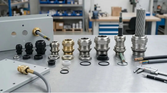
For instrument maintenance, cable glands are indispensable small fittings widely used on transmitters, junction boxes, control cabinets and motor terminal boxes. Though seemingly trivial, they can easily cause confusion during replacement and project procurement when specifications such as M20×1.5, PG13.5, G1/2 and 1/2 NPT appear together.
Reading a cable gland specification can be divided into three dimensions: thread specification for the equipment side, cable clamping range for the cable side, and actual working conditions for application. Matching these three sets of information enables full understanding of the model.
1. Identify the Thread on the Equipment Side
The most commonly encountered specification is M20×1.5. The letter M stands for metric thread; 20 means the nominal thread diameter is 20 mm; 1.5 refers to the pitch of 1.5 mm. These parameters define the interface between the cable gland and the instrument housing. It should be noted that even for the same M20×1.5 interface, cable glands of different series support different cable clamping ranges. The equipment interface and cable compatibility are two independent parameters. If the equipment nameplate or drawing marks M20×1.5, select the corresponding metric gland; for G1/2, choose pipe thread; for 1/2 NPT, select tapered pipe thread. Judgement must be made by combining letters and numbers.
Many flange level transmitters and diaphragm level transmitters on site adopt M20×1.5 metric thread for cable entry. PG series thread interfaces can also be found during revamp of older projects.
Distinguish the Four Common Thread Systems
Four thread families are frequently seen on site: M, PG, G and NPT. G1/2 and 1/2 NPT are the most easily confused. Both carry the marking “1/2”, but they belong to two completely separate thread systems. G1/2 is BSPP parallel pipe thread; 1/2 NPT is American tapered pipe thread. They differ in thread form and sealing principle and are not directly interchangeable. Older equipment may also use PG11, PG13.5 and PG16. PG is the German PG thread system. For maintenance spare parts, it is preferred to keep the original interface specification.
2. Confirm the Cable Clamping Range
After confirming the interface thread, check the cable. Two key points are required: the actual outer diameter of the cable and the clamping range of the cable gland. For example, if the measured cable outer diameter is 8.5 mm and the gland is marked with a clamping range of 6–12 mm, the cable is within the suitable range. If the equipment housing interface is M20×1.5, the matching relationship is clear: M20×1.5 on equipment side, cable outer diameter 8.5 mm.
A common question: “Can I just use an M20 gland?” Thread specification alone is not sufficient. M20 only matches the equipment housing. The clamping range determines whether the cable can be firmly secured and sealed. For remote sealed level transmitters with capillary structures, the outer diameter of signal cables varies, so the clamping range must also be checked during selection.
3. Determine Material and Functions According to Working Conditions
Once the thread and cable parameters are matched, evaluate the application environment. Common cable gland materials include nylon, nickel-plated brass, 304 stainless steel and 316 stainless steel. Indoor control cabinets, open-air installations, humid locations and corrosive process sites have different requirements for material and ingress protection rating. Selection shall comprehensively consider ambient temperature, corrosion, mechanical protection and project specifications.
Additional functional requirements can be added on this basis: EMC shielding structure for shielded cables; armour clamping size for armoured cables. For hazardous areas, explosion-proof type, certification and installation requirements must be verified step by step for a clear selection logic.
4. Hazardous Areas: Extra Notes for Explosion-proof Cable Glands
In explosion-risk applications, cable glands are integral components of the explosion-proof installation system. The equipment interface, cable size and explosion-proof requirements must all match. Clause 6.4.2 of the current mandatory standard GB 3836.15-2024 Explosive atmospheres – Part 15: Electrical installations design, selection and erection clearly states that cable entry devices shall be selected to match the cable diameter. Three layers of logic apply to explosion-proof cable glands: thread specification defines how it connects to the equipment; clamping range ensures cable grip and sealing; explosion-proof certification and structure determine its eligibility for hazardous locations.
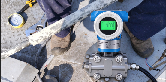
Most tank level transmitters installed on chemical storage tanks are located in explosion hazardous areas. Cable gland selection cannot rely only on thread dimensions; cable outer diameter and explosion-proof certificates are equally important.
5. Complete Selection Example
Take an on-site radar level transmitter as an example: cable entry port M20×1.5, cable outer diameter 8.5 mm, outdoor installation.
1. Equipment side thread: M20×1.5
2. Cable side: clamping range must cover 8.5 mm
3. Housing material and protection grade determined by outdoor conditions
4. If installed in an explosive hazardous area, further verify explosion-proof type, gland certification, cable construction and installation requirements
Recommended sequence for full selection parameters: Thread specification → Cable outer diameter → Clamping range → Material → Protection grade → Additional functions (EMC, armour, explosion-proof).
Sample record: M20×1.5, cable OD 8.5 mm, clamping range covering cable, material compatible with service conditions, protection grade meeting equipment requirements, explosion-proof / armour / shielding added as required. Complete parameter records facilitate procurement, installation and spare parts verification later.
6. Summary
Three core dimensions for reading cable gland models: thread on equipment side, cable diameter on cable side, working conditions on application side. M, PG, G and NPT control the mating with equipment housing; clamping range guarantees cable fixing and sealing; material, protection rating, explosion-proof performance and EMC features adapt to site environments.
When you see M20×1.5, PG13.5, G1/2 or 1/2 NPT, do not judge only by the numbers. Combine equipment interface, cable outer diameter and site conditions to avoid selection mistakes.
As a level transmitter manufacturer, Auto Instrument clearly marks the cable entry thread specification on the nameplate and documentation of our differential pressure level transmitter series. This helps customers select matching cable glands and reduces errors during spare parts procurement.