



Practical Operation Guide for Industrial Instruments: Standard Installation Key Points of Pressure Transmitter Pressure Taps
2026-08-06 10:11Practical Operation Guide for Industrial Instruments: Standard Installation Key Points of Pressure Transmitter Pressure Taps
Introduction
During on-site technical inspections of chemical, oil and gas projects, it is found that the root cause of metering distortion for a large number of absolute pressure transmitters lies in non-standard opening, orientation and straight pipe section installation of pressure taps. This paper unifies standardized construction specifications for pressure taps to solve frequent on-site faults including signal fluctuation, measurement deviation and impulse line blockage of capacitance pressure transmitters, digital pressure transmitters, smart pressure transmitters and OEM pressure transmitters.
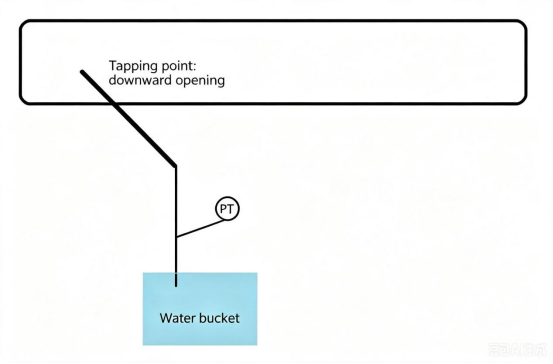
I. Core Fact: The Pressure Tap Is the First Signal Collection Node of the Entire Pressure Measurement System
In the pressure measurement loop composed of absolute pressure transmitters, impulse lines and root valves, the pressure tap is in direct contact with process media. The opening position, angle and inner wall flatness will directly change the flow field. Even if high-precision capacitance pressure transmitters and digital pressure transmitters are adopted, substandard construction of pressure taps will lead to long-term metering errors.
Over 60% of transmitter maintenance work orders in chemical, gas and paper-making projects stem from construction defects of pressure taps.
Complete signal transmission logic: Process medium → Pressure tap → Root valve → Impulse line → Absolute pressure transmitter. The pressure tap serves as the first critical link determining the authenticity of raw pressure signals.
II. Core Practical Highlights (Applicable to All Working Conditions of Smart Pressure Transmitters and OEM Pressure Transmitters)
Mandatory standards for straight pipe sections: Pressure taps must be arranged on stable straight pipes free of eddies, far away from elbows, tees, pump and compressor outlets. For regulating valves, the upstream straight pipe length shall be no less than 2 times the pipe diameter and the downstream length no less than 3 times the pipe diameter; the straight pipe length in front of elbows shall reach 5D. Flow conditioners shall be equipped when space is limited to ensure stable pressure measurement of all types of absolute pressure transmitters.
Orientation rules classified by medium: Open holes at the top of gas pipelines, within 45° horizontal side of liquid pipelines and obliquely above steam pipelines to avoid impulse line blockage caused by condensate and impurity accumulation, enabling long-term stable operation of smart pressure transmitters and OEM pressure transmitters.
Control of hole opening process: The hole diameter ranges from 4 mm to 10 mm; the inner wall shall be completely flush with the pipe wall without burrs or protrusions. Thermal cutting is prohibited, and mechanical drilling is adopted to prevent flow field distortion and continuous value drift of capacitance pressure transmitters.
Mandatory configuration of root valves: Primary valves shall be installed close to all pressure taps to facilitate offline maintenance and pipeline blowdown of digital pressure transmitters without full-line shutdown, greatly reducing factory maintenance and production halt costs.
Component arrangement sequence: Pressure taps on the same pipe section shall be arranged upstream of temperature measuring elements to avoid eddy current interference on raw pressure signals generated by temperature measuring parts, realizing accurate signal collection of smart pressure transmitters.
III. Application Value: Reduce After-sales and Shutdown Losses of Factory Instruments
Factories generally adopt mass configuration of capacitance pressure transmitters and digital pressure transmitters. Standardized construction of pressure taps brings three major benefits:
Sharply cut down transmitter fault work orders: Eliminate signal fluctuation, zero drift and impulse line blockage, and lower logistics costs for instrument after-sales trips.
Stable trade metering data: No measurement deviation for absolute pressure transmitters supporting external sales measurement in oil, gas and chemical industries, avoiding disputes during trade reconciliation.
Extend instrument service life: Reduce the entry of impurities and condensate into transmitter diaphragms, prolong the service cycle of OEM pressure transmitters, and adapt to complex working conditions of high temperature and corrosion.
For special working conditions such as flue gas, dust and high-viscosity slurry, standardized pressure taps matched with corresponding dedicated transmitters can save labor costs from frequent purging and disassembly cleaning.
IV. Supplementary Installation Specifications for Segmented Working Conditions
Media containing solids/dust: For vertical pipelines, pressure taps shall be inclined upward at more than 30°; for horizontal pipelines, holes shall be opened at an acute angle along the flow direction to prevent material accumulation and hole blockage. Absolute pressure transmitters shall be purged regularly through root valves.
High-temperature steam working conditions: Condensation bends shall be installed at the rear end of pressure taps to avoid direct impact of high-temperature media on sensing diaphragms and prevent aging damage under high temperature.
Low-pressure clean room and furnace working conditions: Keep the installation height of pressure taps consistent with transmitters to eliminate interference from liquid column pressure difference and maintain stable zero point of micro-pressure capacitance pressure transmitters without offset.
Differential pressure matched throttling devices (orifice plates, Venturi tubes): The diameter of upstream and downstream pressure taps is uniformly 4–10 mm, and the axis is perpendicular to the pipeline to guarantee accurate differential pressure collection of matched differential pressure transmitters.
V. Common On-site Installation Errors
Pressure taps arranged at elbows or pump outlets, resulting in disordered flow fields and continuous severe value fluctuation of smart pressure transmitters;
Holes opened at the bottom of liquid pipelines, causing impurity accumulation to block impulse lines and long-term inaccuracy of absolute pressure transmitters;
Omission of root valves, leading to full-line shutdown once transmitters break down;
Protruding inner walls or burrs on pressure taps forming local eddies and interfering with measurement of capacitance pressure transmitters;
Temperature measuring elements arranged upstream of pressure taps, blocking fluid and distorting pressure signals.
VI. Standardized On-site Acceptance Checklist
✅ Pressure taps arranged on stable straight pipes with compliant front and rear straight pipe section dimensions
✅ Pressure tap opening orientation matches media: Top for gas, side for liquid, obliquely above for steam
✅ Pressure tap diameter 4–10 mm with smooth, flush inner walls free of protrusions and burrs
✅ Pressure taps located upstream of temperature measuring elements
✅ Root valves equipped close to pressure taps for isolation and maintenance
✅ Condensation bends configured for high-temperature working conditions and purging ports reserved for dusty environments
✅ Range of matched absolute pressure transmitters consistent with on-site static pressure
VII. Conclusion of Full Text
The core source of measurement accuracy for the complete pressure transmitter system lies in standardized construction of pressure taps. When factories select capacitance pressure transmitters, digital pressure transmitters, smart pressure transmitters and OEM pressure transmitters, they must strictly follow three mandatory standards including straight pipe sections, opening orientation and root valves. This fundamentally eliminates hidden dangers such as metering deviation, pipeline blockage and instrument damage, and cuts factory instrument maintenance and shutdown losses.