


Pipe Instrument Installation Layout Standards: Solving Data Drift and Fluctuation of Pressure, Temperature and Flow
2026-08-06 09:18Pipe Instrument Installation Layout Standards: Solving Data Drift and Fluctuation of Pressure, Temperature and Flow
Introduction
During the commissioning of chemical, water supply, power and automation projects, newly calibrated and qualified pressure transmitters, temperature instruments and flow meters often suffer from data drift, value fluctuation or measurement distortion after installation. Most of these faults are not caused by inherent quality defects of instruments, but result from unreasonable arrangement sequence and non-standard installation positions of pipelines, valves, measuring points and flow meters, which lead to turbulent flow fields and damaged measurement conditions. Combined with frontline practical experience, this paper elaborates the standard layout logic of four core pipeline components (valves, pressure transmitters, temperature instruments and flow meters), and provides a complete solution to unstable instrument readings.
1 Common On-site Situation: Abnormal Instrument Readings Rarely Stem from Equipment Faults
Similar problems exist in many projects: the instruments pass factory calibration and are brand new without damage, yet after commissioning, flow readings fluctuate irregularly and drastically, pressure values oscillate continuously, and temperature measurement lags and distorts. Technicians repeatedly inspect instrument bodies, power supply lines, signal loops and grounding systems, but fail to locate the root cause.
A core factor easily overlooked is the wrong arrangement sequence of pipeline components and improper installation positions of sensors, as valves and various pipe fittings generate fluid disturbance. Stable working conditions are a prerequisite for accurate instrument measurement. If the installation position disrupts fluid flow patterns, even ultra-precise instruments cannot output accurate data, which may further cause unstable system control, false interlock trips and severe deviation of process parameters from standard values.
2 Core Principles for Standard Layout: Prioritize Avoiding Mutual Interference Between Components Instead of Simply Following Upstream-Downstream Sequence
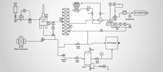
The general layout sequence shown in conventional pipeline drawings is: upstream valve → pressure transmitter → temperature measuring point → flow meter → downstream valve. This sequence only serves as a basic reference template and cannot adapt to all media and flow meter types. Liquid, gas and steam feature vastly different fluid properties; vortex, electromagnetic, orifice plate, turbine and mass flow meters have distinct requirements for straight pipe section length, flow pattern and full-pipe working condition.
A scientific and reasonable layout idea centers on the flow meter: stabilize the flow field around the flow meter first, then arrange pressure transmitters, temperature sensors and various valves accordingly. Elbows, tees, reducers, regulating valves and pump outlets produce turbulence, eddies and pressure pulsations, which are major triggers of measurement data drift. Before finalizing the layout scheme, confirm the medium type, flow meter model, required straight pipe section length and whether temperature & pressure compensation is needed, then complete the overall layout design based on the above factors.
III Valve Installation Specifications: Forbid Direct Installation Upstream of Flow Meters
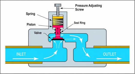
Regulating valves, globe valves, half-open butterfly valves and ball valves are major sources of pipeline fluid disturbance. Throttling by valves generates eddies, turbulence and pressure pulsations, directly causing violent fluctuation of flow measurement values.
Optimal installation scheme: All regulating valves shall be uniformly installed downstream of flow meters to ensure no throttling interference and stable flow field upstream of flow meters, so as to guarantee accurate and stable measurement data.
If limited on-site space forces valves to be installed upstream, the upstream straight pipe section must be greatly extended, and flow conditioners shall be installed as required to eliminate fluid disturbance and prevent measurement distortion caused by face-to-face valve installation. Block valves are only used for maintenance isolation and shall not occupy the effective straight pipe section required by flow meters.
IV Pressure Tap Layout Specifications: Prevent Gas Accumulation, Liquid Build-up, Pipeline Blockage and Signal Lag
Most pressure data drift issues arise from improper pressure tapping methods and unreasonable layout of differential pressure impulse lines, rather than faults of pressure transmitters themselves.
- Liquid medium: Avoid the highest points of pipelines for pressure taps to prevent gas accumulation that delays pressure transmission and causes data drift; for media containing solids or easy to crystallize, avoid the lowest pipeline points to prevent sediment clogging impulse lines. Impulse lines shall maintain an appropriate slope for air venting and liquid drainage.
- Gas medium: Avoid the lowest pipeline points for pressure taps to prevent condensate accumulation leading to falsely high and frequently fluctuating pressure readings; long-term liquid deposition will also corrode impulse lines.
- Steam medium: High-temperature steam must not directly contact pressure transmitters. Isolation components such as condensate collectors, condensate pots and siphon tubes must be equipped to resist high temperatures. Heat tracing and anti-freezing structures shall be added in low-temperature working areas to avoid pipeline freeze blockage and measurement failure.
V Temperature Measuring Point Layout Specifications: Measure Mainstream Medium Temperature Instead of Pipe Wall Temperature
Temperature measurement is highly prone to "false data". Most field thermometers have insufficient insertion depth and only capture the low-temperature area on the pipe wall, failing to detect the mainstream medium temperature at the pipeline center, which ultimately results in low measured temperature values, slow response and distorted measurement results.
Standard installation requirements: Keep temperature sensors away from pump outlets, heat exchanger outlets and local turbulent zones to ensure full medium mixing; the insertion depth of sensors must reach the mainstream area of pipelines; small-diameter pipelines adopt inclined installation or reverse-flow installation at elbows; for large-diameter and steam pipelines, verify the strength of protection sleeves and assess vibration fracture risks to avoid temperature measurement failure.
If temperature measuring points are used for flow temperature & pressure compensation, they must be installed strictly at positions specified by equipment manufacturers without arbitrary modification.
VI Flow Meter Installation: The Highest-Priority Equipment with Strictest Installation Requirements in the Whole System
Flow meters impose the most installation restrictions among all pipeline instruments and are highly sensitive to straight pipe sections, flow patterns, full-pipe conditions, vibration, condensation and pressure pulsation.
Key installation notes: No elbows, tees, reducers or throttling valves shall be arranged upstream; reserve straight pipe sections with lengths complying with manufacturer requirements; keep liquid pipelines fully filled to avoid cavitation and vaporization at high points; prevent liquid accumulation and impact from pressure pulsation in gas pipelines; stay away from water accumulation, strong vibration and sharp temperature change areas for steam pipelines.
Flow meter selection and installation shall prioritize matching on-site working conditions rather than simply pursuing high precision. Even instruments with ultra-high precision cannot operate stably if installation conditions fail to meet standards.
VII Differential Layout Standards for Different Media: Separate Arrangement for Liquid, Gas and Steam
Liquid Pipelines
Ensure full pipeline filling without air bubbles as a priority. Install flow meters on rising pipelines, low pipeline points or areas with stable backpressure; forbid installation on suspended high pipeline points to avoid flow fluctuation caused by negative pressure cavitation.
Supporting measuring instruments for liquid working conditions:
4-20mA pressure transmitter, industrial pressure transmitter, online density meter, industrial online liquid density meter, slurry density meter
Gas Pipelines
Focus on avoiding condensate accumulation and pressure pulsation, reserve sufficient liquid drainage space, and stay away from turbulent areas downstream of compressors and regulating valves.
Supporting measuring instruments for gas working conditions:
gas pressure transmitter, HART pressure transmitter, chemical density meter
Steam Pipelines
Take high temperature, condensation, vibration and temperature & pressure compensation into comprehensive consideration; equip pressure taps with condensate protection structures, arrange temperature sensors in mainstream areas, and install flow meters far from water accumulation and strong vibration sources to guarantee accurate measurement.
Supporting measuring instruments for steam working conditions:
steam pressure transmitter, differential pressure level transmitter
Conclusion
Unstable readings of pipeline instruments do not root in instrument precision, but in installation technology and overall layout logic. Valves determine flow field status, pressure tapping modes affect measurement authenticity, sensor insertion depth decides temperature measurement accuracy, and straight pipe sections guarantee stable flow measurement. Standardized instrument layout is more than simply adjusting front-back sequence; it requires comprehensive design combined with fluid working conditions, measurement principles and on-site service environments. A well-designed layout fundamentally stabilizes instrument readings; unreasonable layout makes later parameter correction and equipment maintenance ineffective in thoroughly solving data drift problems.