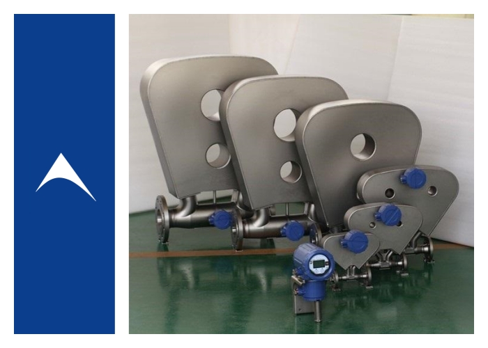
Precautions for Installing Mass Flow Meter & How to Choose Regulating Valve?
2025-07-17 13:25
What are the precautions for mass flow meter installation?
Proper installation of mass flow meter is the key to successful operation. Attention should be paid to:
1. Entrained bubbles. When used for liquid flow measurement, the mass flow meter will stop working when the mist gas content exceeds 1%~5% by volume. These bubbles attenuate the vibration of the flow tube used to generate Coriolis force, and the gas should be eliminated before the sensor.
2. Sediment and suspended matter. The mass flow meter can calculate the mass content of one component in a two-component solution or slurry. Accurate density measurement must avoid the following situations: sediment adheres to the measuring tube wall or solid particles settle out of the suspension (flow rate is too low).
3. Installation direction. The mass flow meter can be installed on horizontal or vertical pipes. The installation direction depends on the application. Some geometric mass flow meters (except straight pipes) will gather some solids or gas phases in a certain installation direction. If vertical installation is required and the fluid flows from top to bottom, measures must be taken to ensure that gas cannot enter the sensor from the sensor inlet pipe.
4. Support. Excessive mechanical stress during sensor installation will affect the zero point of the mass flow meter. If these stresses are constantly changing, the instrument will have unacceptable zero drift. The sensor should be supported by the pipeline system. The flanges should be concentric to avoid compression, bending or twisting. The pipe supports should be as close to the inlet and outlet flanges as possible, and these supports should be attached to a common structure.
5. Vibration. The introduction of the double-tube design greatly reduces but does not completely eliminate the impact of common mode vibration on the mass flow meter. External vibration introduced by the pipeline system can cause the sensor to vibrate in an unexpected way. If the external vibration frequency is equal to or close to the frequency of the sensor drive system, it will interfere with the instrument's drive control system, causing the flow tube to vibrate unstably or stop.
Select the appropriate air-open and air-close form of the regulating valve
① Reactor feed flow regulating valve --- air-open type
② Catalyst feed regulating valve --- air-open type
③ Heat exchanger cooling fluid is water regulating valve --- air-close type
④ Distillation tower top pressure regulating valve --- air-close type
