Working principle and installation requirements of flowmeter - electromagnetic flowmeter
2025-07-11 15:07
Left force, right electricity (that is, the left hand rule determines the direction of force, and the right hand rule determines the direction of current (four fingers)). The measurement principle is based on Faraday's electromagnetic induction theorem, that is, when a conductive liquid flows through an electromagnetic flowmeter, a voltage proportional to the average flow velocity V (volume flow) will be generated in the conductive liquid. Its induced voltage signal is detected by two electrodes in contact with the liquid and converted into a unified output signal by an amplifier. The installation of the electromagnetic flowmeter must ensure the measurement accuracy of the electromagnetic flowmeter. Correct installation is very important.
①. The electromagnetic flowmeter should be installed in a dry and ventilated place. Avoid installing it in a place with too high an ambient temperature. It should not be subjected to strong vibration and vibration. Try to avoid equipment with a strong magnetic field, such as large motors, transformers, etc. Avoid installing it in places with corrosive gases. The installation location is convenient for maintenance. This is the environmental condition to ensure the normal operation of the transmitter.
②. In order to ensure that the measuring tube of the electromagnetic flowmeter is filled with the measured medium, the transmitter is best installed vertically, and the flow direction is from bottom to top. Especially for liquid-solid two-phase flow, it must be installed vertically. If only horizontal installation is allowed on site, it is necessary to ensure that the two electrodes are on the same horizontal plane.
③. Valves and bypasses should be installed at both ends of the electromagnetic flowmeter.
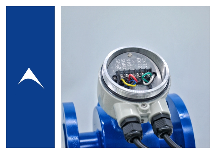
④. The millivolt AC potential measured by the electrodes of the electromagnetic flow transmitter is based on the liquid potential in the transmitter. In order to stabilize the liquid potential and keep the transmitter and the fluid at the same potential to ensure stable measurement, the transmitter housing and both ends of the metal pipe should be well grounded, and the converter housing should also be grounded. The grounding resistance cannot be greater than 10, and it cannot be shared with the grounding wire of other electrical equipment. If it cannot be guaranteed that the transmitter housing is in good contact with the metal pipe, use a metal wire to connect them and then reliably ground them.
⑤. In order to avoid interference signals, the signal between the transmitter and the converter must be transmitted with a shielded wire. It is not allowed to place the signal cable and the power cable in parallel in the same cable steel pipe. The length of the signal cable should generally not exceed 30 m.
⑥. The installation site of the converter should avoid strong AC and DC magnetic fields and vibrations, the ambient temperature should be -20-50℃, no corrosive gases, and the relative humidity should not be greater than 80%.
⑦. In order to avoid the influence of velocity distribution on measurement, the flow control valve should be set at the downstream of the transmitter. For small-diameter transmitters, since the distance from the electrode center to the inlet of the flowmeter is equivalent to several times the length of the diameter D, there is no requirement for the upstream straight pipe. However, for flowmeters with larger diameters, there should generally be a straight pipe section of more than 5D-10D upstream, and a 2D straight pipe section downstream.
