



Differential Pressure Transmitters: Beyond Differential Pressure Measurement — Full Analysis for Flow, Level, Filters and Micro‑Differential Pressure
2026-08-19 10:48Differential Pressure Transmitters: Beyond Differential Pressure Measurement — Full Analysis for Flow, Level, Filters and Micro‑Differential Pressure
Abstract
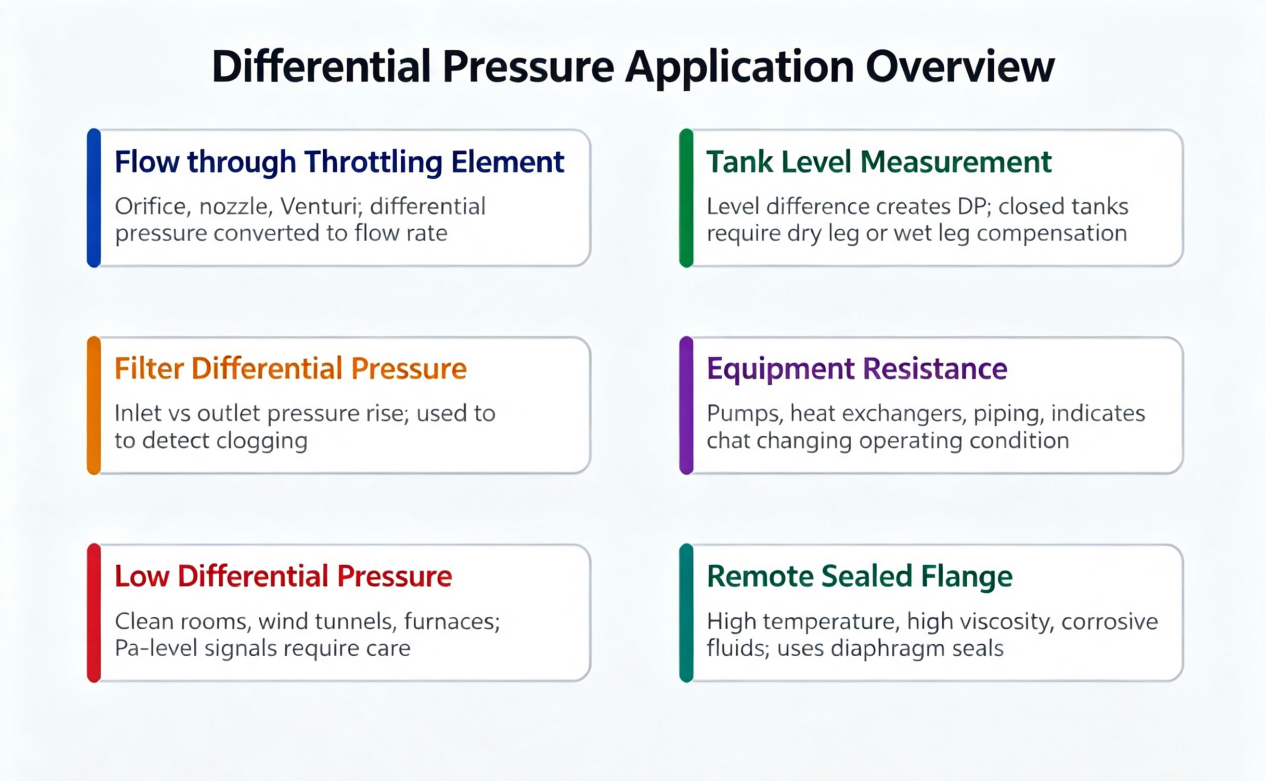
A differential pressure transmitter essentially measures the pressure difference between two pressure‑tapping points, calculated as pressure on the high‑pressure side minus pressure on the low‑pressure side. A common on‑site mistake is equating raw differential pressure directly to flow rate, liquid level, or filter element clogging level. Differential pressure signals support multiple measurement applications, including orifice‑plate flow, Venturi flow, filter differential pressure, closed‑tank liquid level, remote‑seal flange level, cleanroom micro‑differential pressure, furnace negative pressure, and pump inlet‑outlet differential pressure. Combining field identification, product selection and troubleshooting, this paper provides a comprehensive introduction to smart pressure transmitters and their matched instruments.
Differential pressure transmitters are widely deployed across industrial sites, yet their full value is often underestimated.
Some technicians treat them merely as general‑purpose industrial pressure transmitters with two ports;
Some only remember the High (H) and Low (L) pressure sides;
Others associate differential pressure transmitters exclusively with orifice‑plate flow measurement.
None of these interpretations are wrong, yet they remain incomplete.
The core strength of a differential pressure transmitter lies in measuring one fundamental physical quantity: the pressure difference between two points. Through process conversion, this differential pressure can be converted into flow rate, liquid level, medium resistance, cleanroom differential pressure, filter clogging level, furnace negative pressure, or equipment operating conditions.
Accordingly, when inspecting a differential pressure transmitter on site, measuring range should not be the only question.
One critical question must be clarified first:
What process parameter does this differential pressure represent?
Figure 1: Measurement logic of differential pressure transmitters. Core formula = High‑side pressure − Low‑side pressure
1. What Exactly Does a Differential Pressure Transmitter Measure?
Differential pressure transmitters are fitted with two pressure‑tapping ports:
High‑pressure side, generally marked H
Low‑pressure side, generally marked L
Core output formula:
Differential Pressure = Pressure at High‑pressure Port − Pressure at Low‑pressure Port
Positive differential pressure occurs when high‑side pressure exceeds low‑side pressure.
Negative differential pressure occurs when high‑side pressure falls below low‑side pressure; the transmitter outputs within the reverse measuring range.
Though the formula appears simple, most field faults stem from poor understanding of this principle.
The transmitter itself cannot identify whether ports connect to orifice plates, filters, storage tanks or ventilation ducts. It only detects the pressure difference across H and L terminals. Conversion from differential pressure to flow, level, resistance or room differential pressure relies on process mathematical models, transmitter configuration, PLC logic and HMI visualization.
Four critical pieces of information must be confirmed for every differential‑pressure measurement loop:
Connection point of the high‑pressure port
Connection point of the low‑pressure port
Process meaning represented by positive differential pressure
Conversion formula between differential‑pressure range and engineering units
If any item remains unclear, signal reversal faults are highly likely even with sound wiring and commissioning.
2. Why Can One Differential‑Pressure Setup Serve Multiple Measurement Scenarios?
The industrial value of differential pressure comes from its direct reflection of process resistance or liquid‑column height:
Fluid passing through pipe throttling components generates pressure loss proportional to flow rate.
Rising differential pressure across a filter indicates clogged filter elements and contaminated media.
Differential pressure between tank bottom and tank top directly corresponds to liquid‑column height inside the tank.
Low‑pressure applications such as air ducts, cleanrooms and furnaces rely on Pascal‑level micro‑differential pressure to judge ventilation balance and indoor‑outdoor pressure gradients.
Simply put, differential pressure transmitters act as base sensors for multiple measurement solutions.
By pairing with diverse primary elements, pressure‑tapping structures, isolating diaphragms, remote‑seal flanges and calculation logic, one differential pressure transmitter adapts to varied field conditions. High‑temperature pressure transmitters and HART pressure transmitters are mainstream industrial instruments with strong sales across Southeast Asian, South American chemical, food and petrochemical sectors. Most instrument manufacturers supply 4‑20 mA communication versions.
3. Differential‑Pressure Flow: The Most Typical Derived Application
Differential‑pressure flow measurement is the dominant use case for differential pressure transmitters.
Primary elements including orifice plates, nozzles, Venturi tubes, averaging pitot tubes and pitot tubes create pressure loss as fluid flows through. The differential pressure transmitter captures differential pressure, while the control system converts readings into flow. Field installations frequently use complete sets with 4‑20 mA pressure transmitters.
Key On‑Site Notes
Flow rate and differential pressure have a non‑linear relationship. Most throttling devices require square‑root extraction.
Square‑root calculation must be performed in only one location: either inside the transmitter or within the PLC/DCS. Dual‑side square‑root computation is forbidden.
Built‑in transmitter square‑root combined with repeated PLC square‑root causes distortion of low‑flow readings.
Treating differential pressure as linear flow yields massive metering deviation.
During loop commissioning, confirm whether the smart pressure transmitter outputs raw differential pressure or square‑root‑processed flow signals.
4. Differential‑Pressure Level Measurement: Open Tanks, Closed Tanks and Remote‑Seal Flange Solutions
Open Storage Tanks
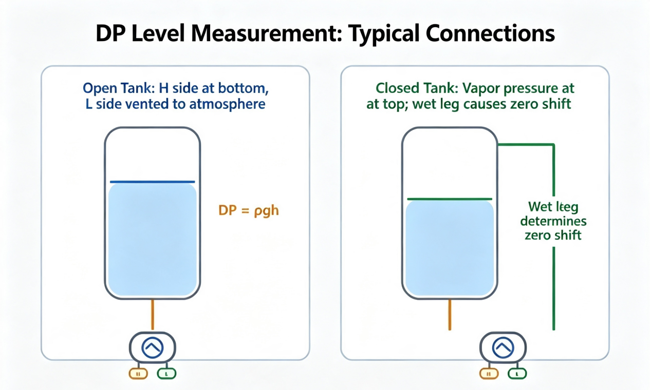
High‑pressure port connects to tank bottom; low‑pressure port vents to atmosphere. Differential pressure rises alongside liquid level. Monitoring can be completed with standard industrial pressure transmitters.
Closed Storage Tanks
Gas‑phase pressure acts equally on the tank‑top tapping point, so differential pressure reflects only liquid‑column height. HART‑protocol transmitters are required for accurate zero‑point suppression.
Remote‑Seal Flange Configuration
Capillary‑style assemblies paired with high‑temperature pressure transmitters are used for high‑temperature, corrosive or viscous media. They prevent impulse‑line blockage and medium crystallization, yet temperature‑induced zero drift requires compensation.
Differential‑pressure level instrument selection must account for medium density, operating pressure and zero suppression. Range‑only selection commonly produces inaccurate metering.
5. Filters, Pumps and Heat Exchangers: Monitoring Equipment Health via Differential Pressure
Rising filter differential pressure signals filter‑element clogging; pump inlet‑outlet differential pressure reflects head variation; elevated differential pressure across heat exchangers indicates scaling and fouling.
Operation‑and‑maintenance teams deploy OEM pressure transmitters for long‑term online monitoring to predict equipment faults in advance.
Pressure‑tapping points shall not sit flush against pipe walls to avoid eddy‑current interference. Blocked impulse lines directly cause invalid instrument readings.
6. Micro‑Differential Pressure: Air Ducts, Cleanrooms, Furnaces and Room Pressure Control
Cleanrooms, dust‑removal ducts and furnaces operate at Pascal‑level micro‑differential pressure with stringent zero‑point stability requirements. Standard industrial pressure transmitters cannot meet specifications; dedicated micro‑differential‑pressure instruments are mandatory.
Door switching, fan start‑stop and condensate accumulation may trigger reading fluctuation. Periodic zero‑point calibration is essential for routine maintenance.
7. Common Derived Instruments Built on Differential‑Pressure Principles
Standard Smart Differential Pressure Transmitter: Factory‑fitted with 4‑20 mA HART, globally accepted for projects; supplied in complete sets with assorted smart pressure transmitters.
High‑Temperature Differential‑Pressure Instrument: For steam and high‑temperature process pipelines, matched with high‑temperature pressure transmitters.
HART‑enabled Differential‑Pressure Instrument: Supports remote parameter modification, preferred by Southeast‑Asian and South‑American buyers sourcing HART pressure transmitters.
OEM Custom Differential‑Pressure Instrument: Custom diaphragms and flanges built for site‑specific conditions, suited for bulk factory procurement of OEM pressure transmitters.
Absolute‑Pressure Matched Instrument: High‑pressure closed vessels use absolute‑pressure industrial pressure transmitters to offset ambient atmospheric‑pressure interference.
8. Instrument Selection: Measuring Range Is Not the Only Criterion
Besides differential‑pressure span, verify static pressure rating, medium temperature, corrosive service conditions, explosion‑proof rating and output protocol.
High‑temperature‑steam applications prioritize high‑temperature pressure transmitters.
Overseas foreign‑trade projects mostly adopt HART pressure transmitters.
Bulk plant construction supports custom OEM pressure transmitters.
Standard chemical plants use general‑purpose industrial pressure transmitters.
9. Common On‑Site Operating Pitfalls
Reversed H/L pressure‑tapping ports, yielding negative readings on smart pressure transmitters.
Duplicated square‑root extraction in flow loops leading to severely under‑reported flow values.
Neglecting medium density for level measurement, producing zero drift for HART pressure transmitters.
Improper disassembly‑reassembly of remote‑seal capillaries causing zero shift for high‑temperature pressure transmitters.
Exceeding maximum static‑pressure rating, rupturing diaphragms of OEM pressure transmitters under high‑pressure service.
10. Conclusion
Differential pressure transmitters require system‑level commissioning covering primary elements, impulse tubing, matched smart pressure transmitters, high‑temperature pressure transmitters and HART pressure transmitters. Sole reliance on local display readings frequently creates metering deviations. Mastering the full measurement chain enables accurate flow, liquid‑level and equipment‑differential‑pressure monitoring plus effective fault diagnosis.