



AUTO Instrument Popular Science|Cleanroom DP Alarms: Gauge & DP Transmitters, Avoid Selection Risks
2026-09-21 13:13AUTO Instrument Popular Science|Cleanroom DP Alarms: Gauge & DP Transmitters, Avoid Selection Risks
Introduction
Based on real‑world fault cases from cleanroom sites, AUTO Instrument analyzes the root causes of recurring differential‑pressure alarm trips. Many differential‑pressure drift failures stem not from damaged equipment or abnormal system fans, but from incorrectly selecting a gauge pressure transmitter instead of a differential pressure transmitter in the early‑stage design. This article explains the principle differences and multi‑layer error sources between gauge‑pressure and differential‑pressure transmitters. Combined with the working principle of differential pressure transmitter, it also covers on‑site tips for DP transmitter and pressure transmitter calibration, and provides quick selection criteria to help engineers avoid pitfalls in micro‑pressure‑measurement specification work.
I. Industry Fact: Frequent Differential‑Pressure Alarms Originate from Improper Instrument Selection
Differential‑pressure alarms keep triggering in cleanrooms. Maintenance crews check the HVAC system; damper openings are normal and fan speed stays stable. Even after installing brand‑new transmitters, readings still drift by dozens of Pascals every day, with inconsistent values between morning and afternoon. After reviewing several months of maintenance records, technicians find that the root cause is not on‑site hardware, but a gauge pressure transmitter incorrectly filled in the selection datasheet.
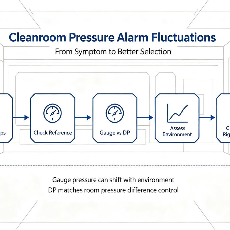
Such issues are common in field applications. Gauge‑pressure transmitters and differential‑pressure transmitters have similar names and small price gaps, so they are easily substituted for one another in procurement. However, their performance differs drastically for micro‑differential‑pressure measurement, resulting in distorted readings and frequent false alarms.
The core sensing component of a transmitter is the pressure‑sensing diaphragm. Its output signal comes from the pressure difference across two sides. Physically, no diaphragm can measure a single absolute pressure value alone. For gauge‑pressure, absolute‑pressure and differential‑pressure transmitters, the only essential difference lies in what the low‑pressure side of the diaphragm connects to.
> A gauge pressure transmitter is essentially a differential pressure transmitter whose low‑pressure side is permanently open to atmosphere; atmospheric pressure is an external variable beyond system control.
As documented in the Rosemount 3051C manual, the isolating diaphragm on the low‑pressure side of model 3051TG gauge‑pressure transmitter opens directly to atmosphere. Its lower‑range limit varies with atmospheric pressure — an inherent reference‑point uncertainty for gauge‑pressure products. Many field drift faults can only be temporarily fixed by performing pressure transmitter calibration.
II. Core Highlights: Three Inherent Errors of Gauge‑Pressure Transmitters Magnified under Micro‑Pressure Conditions1. Reference baseline varies with weather and vent structures are prone to failure
The rear side of the diaphragm inside a gauge pressure transmitter communicates with ambient atmosphere via vent structures. Three common field implementations are: ePTFE‑membrane vent hole, breathing tube, and labyrinth exhaust channel.
Once the breathable membrane gets clogged by oil contamination, dust or paint mist, or freezes / condensates in winter, the pressure inside the reference cavity gets locked at the value at the moment of blockage. Subsequent atmospheric‑pressure changes cannot reach the reference side, manifesting as unexplained zero‑point drift of the transmitter. If a vent hole faces air outlets or louvers, dynamic air pressure will introduce random fluctuations of tens to hundreds of Pascals.
Atmospheric pressure itself fluctuates drastically. Standard sea‑level atmospheric pressure is 101.325 kPa, while practical daily readings range from 98‑105 kPa. Day‑to‑day variation caused by weather systems can reach 2‑3 kPa, further superimposed by altitude effects, atmospheric tides and extreme weather events.
According to ISO 14644‑4, the required differential pressure between adjacent clean‑room classes is merely 5‑20 Pa. When the measured signal is only a dozen Pascals, background atmospheric drift can reach thousands of Pascals. The target signal is completely submerged by atmospheric disturbances, and the transmitter cannot tell whether process differential pressure has changed or outdoor weather conditions have shifted.
2. Full‑span accuracy leads to sharply rising relative errors in micro‑pressure ranges
Accuracy indexes for transmitters, e.g. ±0.1 % FS, are calculated against full‑span (FS) value, independent of the actual measured magnitude.
Constrained by mechanical design, gauge pressure transmitters cannot achieve ultra‑small measuring ranges. Typical inline gauge‑pressure transmitters mostly start at the 10 kPa range level.
Take a 0‑10 kPa transmitter with ±0.1 % FS accuracy as an example: its absolute error is fixed at ±10 Pa. When measuring a 100 Pa micro‑differential‑pressure signal, the relative error hits 10 %, and measurement credibility is largely lost.
3. Zero‑point thermal drift and mounting‑orientation offset introduce secondary interference
Micro‑differential‑pressure measurements operate close to the zero end of the measuring span, where drift influences are most concentrated. For a 10 kPa‑range unit, every 10 °C temperature change brings roughly ±10 Pa zero‑point drift. A 15 °C day‑night temperature swing on‑site yields about ±15 Pa zero shift.
In addition, transmitter mounting orientation creates zero‑point offset. The Rosemount manual records orientation‑induced offset up to approx. 311 Pa for standard models and up to 1243 Pa for remote capillary versions. Such offset can be eliminated via pressure transmitter calibration. However, drift recurs if zero‑point recalibration is skipped after field disassembly‑and‑reassembly for maintenance.
Error‑magnitude comparison between a 0‑10 kPa gauge‑pressure transmitter and a 0‑1 kPa differential pressure transmitter: under 500 Pa working condition, daily atmospheric variation brings ±2000 Pa disturbance to the gauge‑pressure unit, rendering it practically unusable. By common‑mode rejection, the differential‑pressure transmitter cancels atmospheric‑pressure variation, yielding a combined error around 0.4 %. This mechanism can only be understood by learning the working principle of differential pressure transmitter.
III. Scenario Value: Working Mechanism of Differential‑Pressure Transmitters for Micro‑Pressure Measurement & Non‑negligible Application Pitfalls1. Core advantage of differential‑pressure transmitters: common‑mode rejection
From the working principle of differential pressure transmitter: both high‑pressure and low‑pressure sides of a differential pressure transmitter connect to field measuring points. Atmospheric‑pressure changes apply equally to both diaphragms and cancel out after differential calculation:
`(P₁+ΔP_atm)−(P₂+ΔP_atm)=P₁−P₂`
The reference baseline no longer depends on fluctuating ambient atmosphere. Hence the DP transmitter can adopt ultra‑small ranges down to 0‑100 Pa to achieve genuine high‑accuracy micro‑differential‑pressure acquisition. This same principle applies to closed‑tank liquid‑level measurement: the low‑pressure side connects to the tank top gas‑phase space to subtract gas‑phase pressure and obtain pure liquid‑column pressure ρgh.
2. Three critical risks when applying differential pressure transmitters
1) Static‑pressure error: When measuring tiny differential pressure under high line static pressure, static pressure introduces zero‑point and span offset, which is unique to differential pressure transmitters. For high‑static‑pressure applications, check static‑pressure‑error curves and select models with static‑pressure compensation.
2) Impulse‑line liquid‑column and temperature deviation: The two impulse lines must feature equal length, identical temperature and identical elevation. Height difference or temperature mismatch between the two sides produces false differential pressure. Gas‑service lines shall allow self‑draining of condensate; liquid‑service lines shall allow self‑venting of gas bubbles. When zero‑point abnormality occurs, inspect tubing first before performing pressure transmitter calibration.
3) Unidirectional overpressure damaging diaphragms: Micro‑differential‑pressure diaphragms are thin with poor unidirectional‑overload tolerance. Valve mis‑operation or single‑side blockage with subsequent pressure rise may permanently deform or rupture the diaphragm. Strictly follow three‑valve‑group operating logic: open the equalizing valve first and close it last.
3. Quick instrument‑selection guide
✅ Prefer DP (differential pressure transmitter)
Measured signal < 10 kPa; reference pressure itself fluctuates; drift‑to‑signal ratio > 5 %.
Typical applications: clean‑room differential pressure, filter‑cartridge pressure drop, duct differential pressure, closed‑tank liquid level, orifice‑plate flow measurement. Requires dual impulse lines, three‑valve group plus proper heat tracing, draining and venting.
✅ Prefer GP (gauge pressure transmitter)
Measured signal > 100 kPa; reference is definitely atmosphere; drift‑to‑signal ratio < 1 %.
Typical applications: pipeline pressure, pump discharge pressure, open‑tank liquid level. Only single‑point tapping needed for simple installation.
> Intermediate range (10‑100 kPa): Calculate the ratio between background drift and measured signal. Choose differential‑pressure solution if ratio > 5 %. If atmosphere is the confirmed reference and periodic pressure transmitter calibration is acceptable, gauge‑pressure transmitter remains an economical and reliable alternative.
IV. Supplementary Conclusion
The zero‑point reference of a gauge pressure transmitter is tied to variable atmospheric pressure. Atmospheric fluctuation is negligible for high‑magnitude measured pressure, yet becomes the dominant error source for hundred‑Pascal‑class micro‑pressure conditions.
As explained by the working principle of differential pressure transmitter: the DP transmitter switches its reference input to a second process measuring point and eliminates atmospheric interference via common‑mode rejection, enabling accurate micro‑differential‑pressure measurement.
This selection‑related pitfall is highly deceptive. Transmitters come with complete factory certificates and valid output signals; problems do not surface during commissioning. Frequent differential‑pressure‑alarm trips only occur when obvious day‑night or weather‑driven atmospheric shifts take place. During engineering selection work, clarify the application boundaries between gauge pressure transmitter and differential pressure transmitter. Carry out pressure transmitter calibration when necessary to avoid repeated on‑site troubleshooting afterwards.
AUTO Instrument offers a full‑product portfolio of differential pressure transmitters and gauge pressure transmitters. We provide selection support for working conditions including clean‑room micro‑differential pressure, closed‑tank liquid level and pipe‑network pressure, helping avoid hidden risks from improper selection and guarantee long‑term stable operation of measurement systems.